


BUILDING AN LTC1799 OSCILLATOR ON STRIPBOARD.
The Linear Technology LTC1799 is probably the most quick and easy way of adding pitch control to any machine or toy that doesn't have a simple clock resistor. More details of the actual IC and datasheets can be found at the Linear Technology site HERE, but on this page we will be concentrating on building an LTC1799 oscillator on a small piece of stripboard / veroboard.
We also have a general INSTALLATION GUIDE that covers the basics of installing a stripboard based LTC1799 on many machines.
Before you start you'll need the following:
- LTC1799 mounted on a 6 pin DIL adapter.(available in our shop HERE)
- stripboard measuring approximately 5 x 14 holes.
- 100nF ceramic disc capacitor.
- Resistor (see below - value anywhere between 3K and 100K or so, but we recommend you start with 10K).
- Potentiometer (see below - value depends on the application but 470K / 500K is a good start).
- Wire.
- Optional board pins and mounting post.
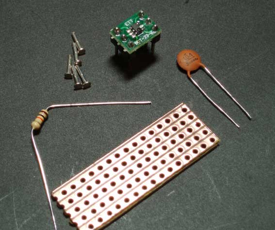
The first thing to do is familiarize yourself with the parts.The capacitor should be labeled '104' and you can check resistor colour codes HERE but there are plenty of other places on the net. The actual LTC1799 is the tiny chip about as big as a grain of rice soldered in the centre of the green adapter board.
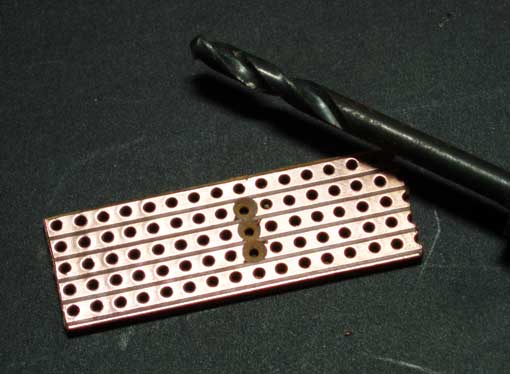
The board layout we use most often is shown below.
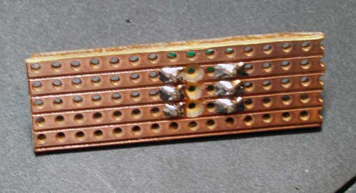
The first thing to note are the square red markings under IC1. These indicate cuts in the tracks which should ideally be done with a handheld track cutting tool, although a drill bit of the correct size will do the same job if you do it by hand. At a push you can just cut the tracks with a sharp knife and peel back the strip a little. Care should be taken that there are no tracks shorted to adjacent ones after the cuts have been done. The red marking to the right indicates where a hole should be drilled if you are using a mounting post.
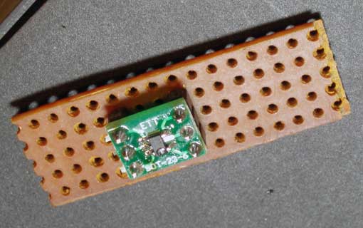
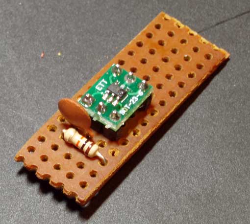
Next you should solder the LTC1799 onto the board as shown on the layout above and the pictures below. Care should be taken to get it the correct way around as otherwise you'll end up with a dead chip. The tiny LTC1799 chip itself has 5 pins which are soldered to the adapter board. With the correct orientation there should be three soldered pins on the left and two on the right, with the text on the adapter the right way up.
The next step is to solder the capacitor and resistor in place. The orientation of these parts is not important as they can be installed either way around. The value of the resistor will depend on the application you are using the oscillator for, but the datasheet recommends a minimum of 3K and a maximum of 1M, although for this job you'd probably never need more than 100K. This resistor acts as an upper frequency limiter to stop the oscillator running too fast for your target machine and causing it to crash, although this can sometimes produce interesting effects. You will have to experiment with different values to find out what works best for your application although 10K is a good starting points. Alternatively you could always install a trimmer / preset pot in place of this resistor and adjust it to get the best value.
If you have some experience with installing this circuit, another option is to start without a resistor in place and just initially solder the lower connection from the pot to the +5v positive rail. This effectively bypasses where the resistor would be, or gives you the equivalent of a zero ohm resistor. With everything correctly wired to the circuit of the unit being clocked, you should be able to run the machine and slowly turn up the clock rate until the machine crashes. Turn off the machine, lower the clock rate very slighty, disconnect the pot from the LTC1799 circuit and then measure the resistance on the pot with a multimeter, You can then install a limiting resistor slightly larger than this value and wire the pot back to the correct pins.