CHIP RISER - IC BREAKOUT BOARDS
These are also available on our ETSY shop for EU customers.
Read more about buying from the EU HERE.
Once again we're elegantly solving problems with an extremely limited sales demographic that you never even knew you had!

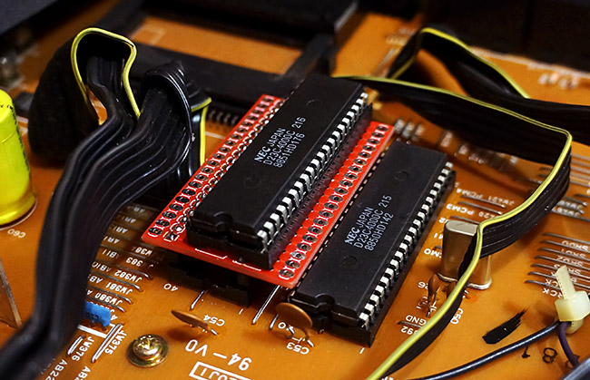
Chip Riser installed with one of the sound ROM's in an AKAI XE8 drum module
Our new chip riser™ PCB's are designed to solve the problem of needing to get at the pins of a socketed chip from the component side of the board, without messily soldering directly to the top side of the pins and ending up either overheating the chip, shorting pins together, or accidentally soldering it into the socket!
Maybe you want to solder to sound ROM or sample RAM chip pins to create some kind of circuit bending patchbay, but you don't want to run a bundle of wiring all the way under the board. Maybe you want to attach test probes to the chip pins but you don't want to solder wiring directly to the pins on the component side. Maybe trying to remove the main board to get at the solder side is a massive pain in the ass, and you need to safely access the pins on the top of the board.
These boards work by simply removing a chip from its socket, plugging it into the chip riser board, and then plugging the whole board back into the vacant socket using the pins on the underside. The unit will then work exactly the same but each pin of the chip is available on a solder pad on either side of the chip riser board. You can solder directly to the pads, solder in header pins, or just use the pads as an easy way to connect probes or test shorts for circuit bent effects.
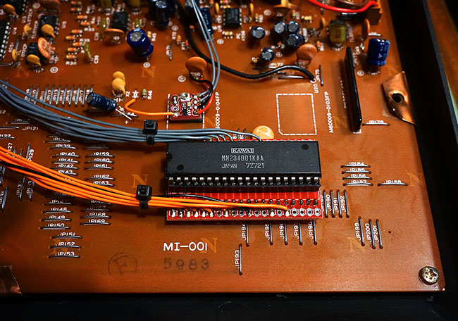
Where space is short for a permanent installation we often just remove a socket from a board and solder a chip riser directly to the PCB in its place.
We only supply the chip riser PCB, so you will also need to source an IC socket of the appropriate size plus two lengths of turned pin headers. For a short build guide take a look HERE.

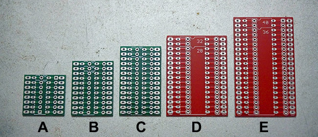
The chip risers come in 5 different sizes:
Most CMOS, DRAM, PIC, AVR etc are covered by the thinner DIL format versions on the green boards:
SIZE A: 14-16 pin
SIZE B: 18-20-22 pin
SIZE C: 24-28 pin
EPROM's, sound ROM's, older RAM, larger microcontrollers etc are covered by the wider DIL format boards in red:
SIZE D: 28-32 pin wide
SIZE E: 36-40 pin wide
When a board covers more than one chip size, just install the size socket you want to use as shown on the board, i.e. on the 18-20-22 board, if you want to use it for a 20 pin chip just install a 20 socket as indicated on the silk screen, and two lots of ten pin strips of header pins underneath in the appropriate places either side. You'll have a couple of pins left over at the top of the board, but its a hell of a lot easier using one board for 2 or 3 different sizes than supplying a different board for every single chip size!
We're selling the size A, B and C in strips of 4 boards for £5 and the larger size D and E boards are 2 boards for £5..
SIZE A: 14-16 PIN - £5 for 4
SIZE B: 18-20-22 PIN - £5 for 4
SIZE C: 24-28 PIN - £5 for 4
SIZE D: 28-32 PIN WIDE- £5 for 2
SIZE E: 36-40 PIN WIDE- £5 for 2


